Sterilization of liquid medium may be defined as the destruction or removal of undesirable microbial contaminants in the medium.
Proper sterilization of fermentation medium plays an important role in guaranteeing the success of industrial pure culture fermentation/bioprocessing.
Available techniques of medium sterilization include the following:
1. Irradiation
2. Freezing
3. Shear
4. High frequency sonic vibrations
5. Heating
6. Chemical treatment
7. Microfiltration
Among all the techniques the most widely practiced technique is the destruction of un-designable microbial contaminants through the application of heat for medium containing less thermolabile components. However, for thermolabile media sterilization microfiltration has been used in practice.
Sterilization Methods:
Media in fermentation industry can be sterilized either by batch or by continuous mode.
Usually most media in bioprocessing/fermentation industry are sterilized by batch method.
1. Batch sterilization of media:
Different types of equipment system for batch sterilization of media have been reported in the literature. Figures below show some typical type of equipment schematics for this purpose.
Methodology:
In current practice thermal sterilization of media is carried out by moist heat of saturated steam. In batch the content is heated by saturated pressurised steam flow through the jacket to the design sterilization temperature (121 °C at 15 psig). When the design sterilization temperature is reached, the medium is held at that temperature for the required design time and then cooled abruptly by flowing chilled water through the jacket instead of steam.
2. Steam sterilization of equipment:
Fermenters and other equipment’s are routinely sterilized by direct steam to reduce any contaminating organism load. Typical conditions are 121 °C (15 – 20 psig steam) for 30 – 60 minutes. Fermenters must be sterilized empty with steam for use with continuous sterilizers, however this is commonly also done in batch sterilization processes to reduce incidental load. Pending use, sterilized vessels should be kept under positive pressure using sterile air. Steam is also used to sterilize air and solution, sterilizing filters and associated transfer piping.
From the experimental time-temperature profile of batch sterilization it can be seen that there are three distinct periods in total sterilization cycle mainly heating up period, holding period and cooling period. In this cycle the initial number of cells (N0) present at the initiation of heating is reduced to N1 at the end of heat up period. Next is the holding period at design sterilization temperature N1 and it is reduced to N2, which is finally brought down to zero or safe number level at the end of abrupt cooling period as shown in the above figure.
It can be seen in the figure that there is continuous decrease in number of viable cells during the sterilization cycle. Therefore destruction of microorganisms by heat implies loss of viability, not destruction in physical sense. It is therefore, necessary to understand the nature of thermal death kinetics of microorganisms in media sterilization.
3. Thermal Death of Microorganisms:
Destruction or death of vegetative microbial cells by heating at a specific temperature follows a monomolecular rate of reaction as follows:
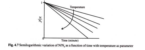
From equation 4.50 if one plots on a semi-logarithmic scale N/N0 against time with temperature as parameter gets the most representative form of linear profile for vegetative cells as shown below.
Slope of this plot is numerically equal to K. Smaller the value of K more resistant the organisms is to thermal death.
However, microbial medium may contain spore as well as contaminants, which need also to be destroyed by heating. It has been proposed by Prokop and Humphery that a sequential step for inactivation of spores occurs during thermal sterilization. A representation of these sequential steps has been given by
Where tt is the time to reach sterilization temp. ts, t2 is the holding time at sterilization temp. ts and t3 is the time to cool from ts to cultivation temperature t3, N0 is the initial number of organisms = VL . N0; in which VL is the volume of the liquid in the fermenter and N0 is the number of organism per unit volume. The drawbacks of batch sterilization relate to scale dependence of Vheat and Vcool. Larger fermenters typically have less heat exchange surface per unit volume and so require longer heat up and cool down times.
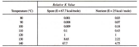
Consequences of long heat up and cool down time can be severe if the medium components are heat labile. This is because B. stearothermophilus is only significantly inactivated above 110°C due to its high activation energy of 67.7 kcal/mole. On the other hand many organic nutrients which also follow the Arrhenius relationship for thermal degradation, have a much lower activation energy of around 25-30 kcal/mole.
This implies that longer exposure to lower sterilization temperature, due to slow heat-up or cool-down can cause proportionately more damage to nutrients. Table 4.1 summarizes the effect of a 1 minute exposure to various temperature on B. stearothermophilus compared to a typical nutrient (E = 25 kcal/mole.)
Table 4.1: Relative degradation rate constants of B. stearothermophilus and typical heat labile nutrient
Residence Time Concept in Continuous Sterilization:
Residence time concept in the pipe flow of continuous sterilizer is important in order to avoid over heating of the medium causing nutritional devaluation. Flow pattern and type are important in ascertaining pipe length and dispersion of fluid (Fig. 4.9). One way to reduce heat up time is to inject steam directly into the medium during sterilization. This will improve the heat up time, but will result in dilution of the media by W factor.
The factor W is computable by the following:
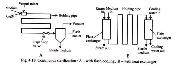
The best alternative for heat sensitive materials is to use continuous sterilization. The basic process is shown in (Fig. 4.10) below. Here the raw medium is slurred in water, and then continuously pumped through the sterilizer to a previously sterilized, empty, fermentor vessel. In the sterilizer the media is instantaneously heated by either direct or indirect steam and held at a very high temperature, typically 140°C, for a short time (typically 30-120 seconds).
This residence time or holding time of the media is fixed by adjusting the flow rate and length of insulated holding pipe. The hot stream from the sterilizer is rapidly cooled by a heat exchanger, (with or without heat recovery) and/or by flash-cooling before it enters the fermentor vessel.
The continuous sterilization process has several advantages:
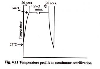
(1) The temperature profile of the medium (Fig. 4.11) is almost one of instant heating and cooling allowing an easy estimate of the Del factor (V) required. This makes scale-up very simple.
(2) The medium is exposed to high temperatures for short times, thereby minimizing nutrient degradation, and
(3) The energy requirements of the sterilization process can be dramatically reduced by using the incoming raw medium to cool the hot sterile media.
The difficulties with continuous sterilizers are typically operational due to exchanger fouling or control instability. In general, media containing solids or starches require attention for continuous sterilization.
The design of continuous sterilizer must allow some flexibility in operating conditions to adapt the system to different media. The system must incorporate automatic recycle to recirculate media if temperature falls below the design value.
The design objectives should include:
1. Ability to fill the fermentor within 2-3 hours,
2. The recovery of 60-70% of the heat,
3. Plug flow in the holding section, and
4. The option of either direct or indirect heating.
Essential components of a continuous sterilizer are shown in Fig. 4.12 and include the batching system, solids separator, batch feed tank, heating section, sterilizing section, cooling system, and back pressure valve. Selection of the heat exchanger is critical to successful operation. Typically double pipe, spiral or plate-frame exchangers are used.
The major design variables in the design of a continuous sterilizer are the sterilization temperature TS, the fluid velocity u, and the length L and diameter d of pipe in the holding section.
For minor deviation from plug flow the Del factor for continuous sterilization is given by:
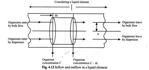
Continuous sterilizers are typically sterilized by recirculating water for an hour. Then batch components are batched and added separately one after the other. Finally the equipment is cleaned by recirculating cleaning solutions. In continuous sterilization in the equipment flow pipe one may consider a liquid element as depicted in the Fig. 4.13.
The equation of flow of a microbial suspension through a tube considering both radial and axial dispersions is given by
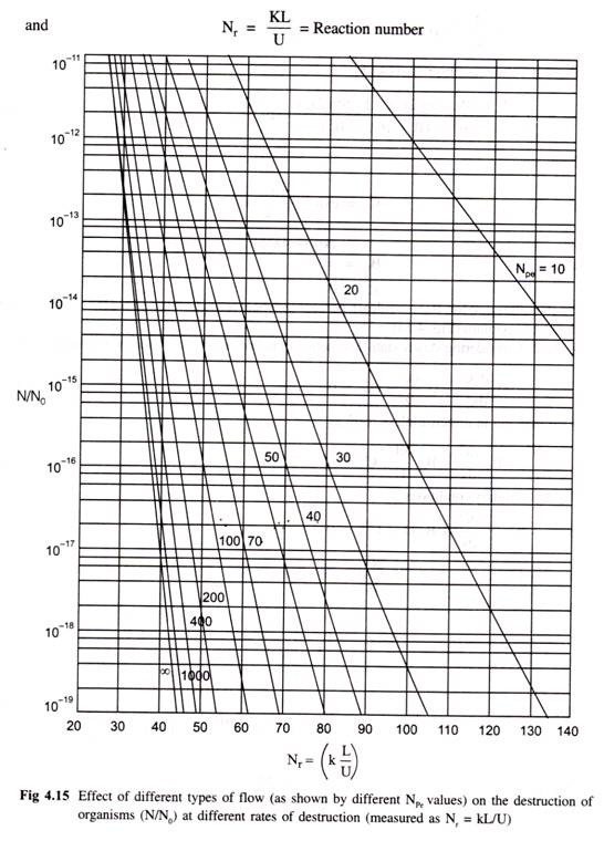
Assuming that microbes behave like molecule as far as diffusion is concerned the solution of equation (4.62) may be obtained considering following two cases.
Case 1: Fraction of material overheated only and no reaction takes place (i.e. KC = 0). When D1 > 10-5 cm2/sec.
![clip_image006[4] clip_image006[4]](https://www.biologydiscussion.com/wp-content/uploads/2015/03/clip_image0064_thumb.jpg)
![clip_image009[6] clip_image009[6]](https://www.biologydiscussion.com/wp-content/uploads/2015/03/clip_image0096_thumb.jpg)
![clip_image011[6] clip_image011[6]](https://www.biologydiscussion.com/wp-content/uploads/2015/03/clip_image0116_thumb.jpg)


![clip_image021[6] clip_image021[6]](https://www.biologydiscussion.com/wp-content/uploads/2015/03/clip_image0216_thumb.jpg)
![clip_image023[6] clip_image023[6]](https://www.biologydiscussion.com/wp-content/uploads/2015/03/clip_image0236_thumb.jpg)
![clip_image025[6] clip_image025[6]](https://www.biologydiscussion.com/wp-content/uploads/2015/03/clip_image0256_thumb.jpg)
![clip_image027[6] clip_image027[6]](https://www.biologydiscussion.com/wp-content/uploads/2015/03/clip_image0276_thumb.jpg)
![clip_image029[6] clip_image029[6]](https://www.biologydiscussion.com/wp-content/uploads/2015/03/clip_image0296_thumb.jpg)
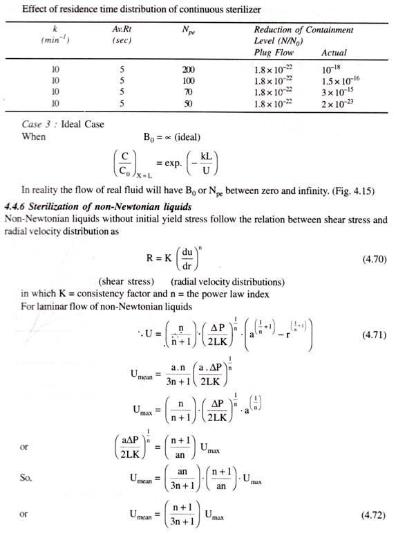
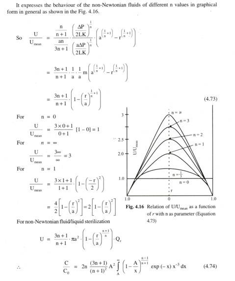
![clip_image037[6] clip_image037[6]](https://www.biologydiscussion.com/wp-content/uploads/2015/03/clip_image0376_thumb.jpg)