This article throws light upon the three methods used for detection and measurement of radioactivity.
The three methods are: (1) Methods Based Upon Gas Ionization (2) Methods Based Upon Excitation and (3) Methods Based Upon Exposure of Photographic Emulsions.
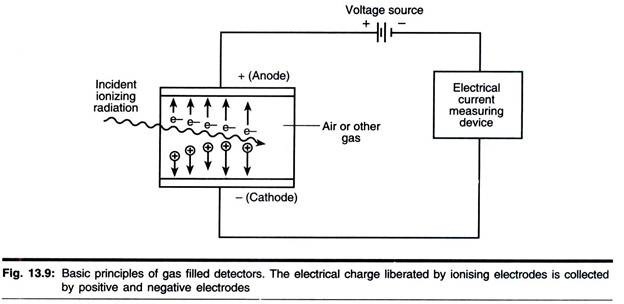
The following figure shows the scheme of basic radiation detector system:
Contents
1. Methods Based Upon Gas Ionization:
The Effect of Voltage Upon Ionization:
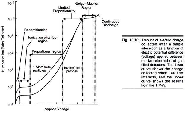
As a charged particle passes through a gas, its electrostatic field dislodges orbital electrons from atoms sufficiently close to its path and causes ionization (Fig. 13.10). The ability to induce ionization decreases in the order
α > β > у (10 000: 100: 1)
Accordingly, α- and β-particles may be detected by gas ionization methods, but these methods are poor for detecting у-radiation. If ionization occurs between a pair of electrodes enclosed in a suitable chamber, a pulse (current) flows, the magnitude of which is elated to the applied potential and the number of radiation particles entering the chamber (Fig. 13.10). The various ‘regions’ shown in Fig. 13.10 will now be considered.
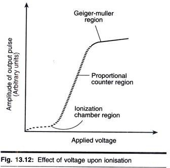
In the ionization chamber region of the curve, each radioactive particle produces only one ion- pair per collision. Hence the currents are low, and very sensitive measuring devices are necessary. This method is little used in quantitative work, but various types of electroscopes, which operate on this principle, are useful in demonstrating the properties of radioactivity.
At a higher voltage level than that of the simple ionization chambers, electrons resulting from ionization move towards the anode much more rapidly; consequently they cause secondary ionization of gas in the chamber, resulting in the production of secondary electrons, which cause further ionization and so on. Hence from the original event a whole torrent of electron reaches the anode. This is the principle of gas amplification and is known as the Towensend avalanche effect, after its discoverer. As a consequence of this gas amplification, current flow is much greater.
As can be seen in Fig. 13.10, in the proportional counter region the number of ion-pairs collected is directly proportional to the applied voltage until a certain voltage is reached, when a plateau occurs. Before the plateau is reached there is a region known as the limited proportion region, which is not often used in detection and quantification of radioactivity and hence will not be discussed.
The main drawback of counters that are manufactured to operate in the proportional region is that they require a very stable voltage supply because small fluctuations in voltage result in significant changes in amplification. Proportional counters are particularly useful for detection and quantification of α-emitting isotopes, but it should be noted that relatively a few such isotopes are used in biological work.
In the Geiger-Muller region all radiated β-particles, induce complete ionization of the gas in the chamber. Thus the size of the current is no longer dependent on the number of primary ions produced. Since maximum gas amplification is realized in this region, the size of the output pulse from the detector will remain the same over a considerable voltage range (the so-called Geiger- Muller plateau). The number of times this pulse is produced is measured rather than its size. Therefore, it is not possible to discriminate between different isotopes using this type of counter.
Since it takes a finite time for the ion-pairs to travel to their respective electrodes, other ionizing particles entering the tube during this time fail to produce ionization and hence are not detected, thereby reducing the counting efficiency. This is referred to as the dead time of the tube and is normally 100 to 200µs.
When the ions reach the electrode they are neutralized. Inevitably some escape and produce their own ionization avalanche. Thus, if unchecked a Geiger- Muller tube would tend to give a continuous discharge. To overcome this, the tube is quenched by the addition of a suitable gas, which reduces the energy of the ions. Common quenching agents are ethanol, ethyl formate and the halogens.
Instrumentation:
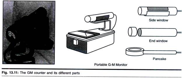
Counters based on gas ionization used to be the main method employed in the quantification of radioisotopes in biological samples. Currently, scintillation counting has virtually taken over. However, all laboratories use small hand-held radioactivity monitors based on gas ionization, the end- window design being the most popular type (Fig. 13.12).
These counters have a thin end-window made from aluminium and can detect β-radiation from high energy (32P) and weak emitters (14C), but are incapable of detecting 3H, because the radiation cannot penetrate the end-window. For the same reason they are not very efficient detectors of α-radiation.
End-window ionization counters are used for routine monitoring of the radioactive laboratory to check for contamination. They are useful in experimental situations where the presence or absence of radioactivity needs to be known rather than the absolute quantity, for example quick screening of radioactive gels prior to autoradiography or checking of chromatographic fractions for the labelled components.
The inability of end-window counters to detect weak β-emitters presents a problem in biosciences because 3H is a very commonly used radioisotope. The problem can be overcome by using a so called windowless counters where a gas flow is used. These instruments are rather cumbersome and need to be carried around on an object that resembles a golf trolley. They are useful for mass screening of premises for 3H contamination but are rarely used as routine. Most laboratories monitor for H by doing a wipe test regularly, i.e., using wet tissues or cotton wool to take swabs for scintillation counting.
2. Methods Based Upon Excitation:
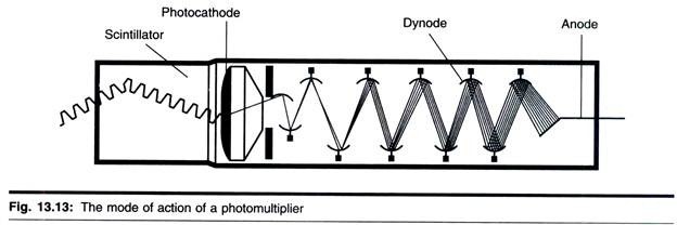
As outlined above, radioactive isotopes interact in matter in two ways, causing ionization, which forms the basis of Geiger-Muller counting, and excitation. The latter effect leads the excited compound (known as fluor) to emit photons of light. This fluorescence can be detected and quantified. The process is known as scintillation and when the light is detected by a photomultiplier, forms the basis of scintillation counting.
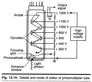
The electric pulse that results from the conversion of light energy to electrical energy in the photomultiplier is directly proportional to the energy of the original radioactive event. This is considerable asset of scintillation counting, since it means that two, or even more, isotopes can be separately detected and measured in the same sample, provided they have sufficiently different emission energy spectra. The mode of action of a photomultiplier is shown in Fig. 13.13.
In summary, scintillation counting provides information of two kinds:
Quantitative:
The number of scintillations is proportional to the rate of decay of the sample, i.e., the amount of radioactivity.
Qualitative:
The intensity of light given out and, therefore, signal from the photomultiplier is proportional to the energy of radiation.
Types of Scintillation Counting:
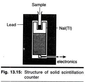
There are two types of scintillation counting, which are described next page. In solid scintillation counting the sample is placed adjacent to a crystal of fluorescent material. The crystal that is normally used for у-isotopes is sodium iodide, whereas for α-emitters zinc sulphide crystals are preferred and for β-emitters organic scintillators such as anthracene are used.
The crystals themselves are placed near to a photomultiplier, which in turn is connected to a high voltage supply and a scaler. Solid scintillation counting is particularly useful for у-emitting isotopes. This is because these rays are electromagnetic radiation and colloid only rarely with neighbouring atoms to cause ionization or excitation. Clearly, in a crystal the atoms are densely packed, making collisions more likely.
Conversely, solid scintillation counting is generally unsuitable for β-emitting isotopes such as 3H and 14C, because even the highest energy negatrons emitted by these isotopes would have hardly sufficient energy to penetrate the walls of the counting vials in which the samples are placed for counting. As many of the isotopes used in radioimmunoassay are y-emitting isotopes, solid scintillation counting is frequently used in biological work.
In details the arrangement and working of solid detectors is explained herewith by the example of Nal detector. In this the quartz window is optically coupled by a light transmitting gel to the face of evacuated electron tube (PMT) which is plugged in to the base designed to supply voltage to various electrode and collect the signal pulse from PMT anode.
The sequence of events is as follows:
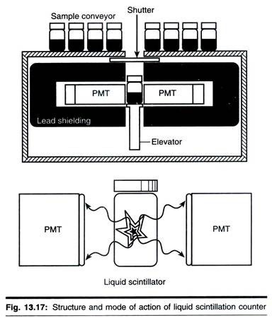
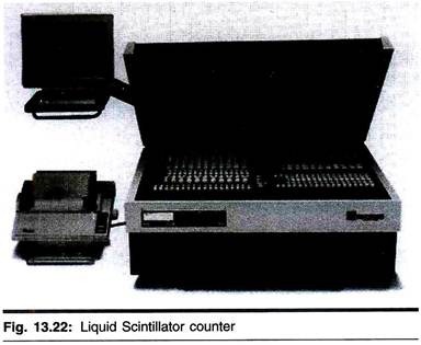
In liquid scintillation counting, the sample is mixed with a scintillation cocktail containing a solvent and one or more fluors. This method is particularly useful in quantifying weak β-emitters such as 3H, 14C and 35S, which are frequently used in biological work. For these isotopes, liquid scintillation counting is the usual method. Thus the remainder of this section will place particular emphasis on this technique, though it should be pointed out that most of what follow applies equally to solid scintillation counting used in the quantification of у-emitters.
Energy Transfer in Liquid Scintillation Counting:
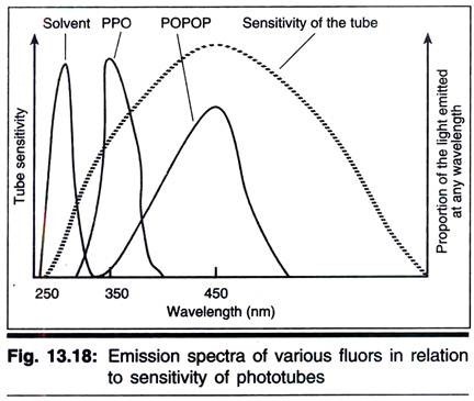
A small number of organic solvents fluoresce when bombarded with radioactivity. The light emitted is of very short wavelength (Fig. 13.18) and is not efficiently detected by most photomultipliers; however, if a compound is dissolved that can accept the energy from the solvent and itself fluoresce at a longer wavelength, then the light can be more efficiently detected.
Such a compound is known as a primary fluor and the most frequently used example is 2, 5-dephenyloxazole (PPO). Unfortunately the light emitted by PPO is not always detected with very high efficiency (depending on the photomultiplier detector) but this can be overcome by including a secondary fluor or wavelength shifter such as 1, 4-bis (5-phenyloxazol-2-yl) benzene (POPOP). Thus the energy transfer process becomes
The question obviously arises as to why a primary fluor and a secondary fluor are necessary when it is the latter that emits light at the best wavelength for detection. The answer is simple that the solvent cannot transfer its energy directly to the secondary fluor.
PPO and POPOP were among the original fluors used in liquid scintillation counting and remain a favourable choice. However, compounds such as 2-(4′-t-butylphenyl)-5-(4″ biphenylyl)-1, 3, 4-oxadizole (BUTYL-PBD) is a better primary fluor but is quiet expensive and is affected by extremes of pH.
Most laboratories now buy their scintillation cocktails already prepared arid there are many different makes and recipes on the market. Competition and an increasing awareness of health and safety mean that scintillation cocktails are gradually becoming less toxic and have a lower fire hazard. A final point: some cocktails (as just described) are designed for organic samples and others for aqueous samples (these cocktails include an emulsifier such as the detergent Triton X-100); it is important that the appropriate formulation is used.
Advantages of Scintillation Counting:
The very fact that scintillation counting is widely used in biological work indicates that it has several advantages over gas ionization counting.
These advantages are listed below:
i. The rapidity of fluorescence decay (10-9s), which, when compared to dead time in a Geiger-Muller tube (10-4s), means much higher count rates are possible.
ii. Much higher counting efficiencies particularly for low energy β-emitters; over 50% efficiency is routine in scintillation counting and efficiency can rise to over 90% for high energy emitters. This is partly due to the fact that the negatrons do not have to travel through air or pass through an end-window of a Geiger-Muller tube (thereby dissipating much of the energy before causing ionization) but interact directly with the fluor; energy loss before the event that is counted is therefore minimal.
iii. The ability to accommodate samples of any type, including liquids, solids, suspensions and gels.
iv. The general ease of sample preparation (see below).
v. The ability to count separately different isotopes in the same sample, which means dual labelling experiments, can be carried out.
vi. Scintillation counters are highly automated, hundreds of samples can be counted automatically and built-in computer facilities carry out many forms of data analysis, such as efficiency correction, graph plotting, radioimmunoassay calculations, etc.
Disadvantages of Scintillation Counting:
It would not be reasonable, having outlined some of the advantages of scintillation counting, to disregard the disadvantages of the method. Fortunately, however, most of the inherent disadvantages have been overcome by improvement in instrument design.
These disadvantages include the following:
i. The cost per sample of scintillation counting is not insignificant; however, other factors including versatility, sensitivity and ease and accuracy outweigh this factor for most applications.
ii. At the high voltages applied to the photomultiplier, electronic events occur in the system that are independent of radioactivity but contribute to a high background counts. This is referred to as photomultiplier noise and can be partially reduced by cooling the photomultipliers. Since temperature affects counting efficiency, cooling also presents a controlled temperature for counting, which may be useful.
Low cost photomultipliers, however, have been designed to provide greater temperature systems. Also the use of a pulse height analyzer can be set so as to reject, electronically, most of the noise pulses that are of low energy (the threshold or gate setting). The disadvantage here is that this also rejects the low energy pulses resulting from low energy radioactivity (e.g., 3H).
Another method of reducing noise, which is incorporated into most scintillation counters, is to use coincidence counting; in this system two photomultipliers are used. These are set in coincidence such as that only when a pulse is generated in both tubes at the same time it is allowed to pass to the scaler.
The chances of this happening for a pulse generated by radioactive event is very high compared to the chances of a noise event occurring in both photomultipliers during the so-called resolution time of the system, which is commonly of the order of 20 ns. In general, this system reduces photomultiplier noise to a very low level.
iii. The greatest disadvantage of scintillation counting is quenching. This occurs when the energy transfer process described earlier suffers interference. Correcting for this quenching contributes significantly to the cost of scintillation counting. Quenching can be am one of three kinds.
(i) Optical quenching:
This occurs if inappropriate or dirty scintillation vials are used. These will absorb some of the light being emitted, before it reaches the photomultiplier.
(ii) Chemical quenching:
This form of quenching, which occurs when anything in the sample interferes with the transfer of energy from the solvent to the primary fluor or from the primary fluor to the secondary fluor, is the most difficult form of quenching to accommodate. In a series of homogeneous sample (e.g., 14CO2 released during metabolism of [14C] glucose and trapped in alkali, which is then added to the scintillation cocktail for counting), chemical quenching may not vary greatly from sample to sample. In these cases relative counting using sample counts per minute can be compared directly.
However, in the majority of biological experiments using radioisotopes, such homogeneity of samples is unlikely and it is not sufficiently accurate to use relative counting (i.e., counts per minute). Instead an appropriate method of standardization must be used. This requires the determination of counting efficiency of each sample and the conversion of counts per minute to absolute counts (i.e., disintegrations per minute), as described later. It should be noted that quenching is not such a great problem in solid (external) scintillation a uniting.
a. Chemiluminescence:
This can also cause problem during liquid scintillation counting. It re suits from chemical reactions between components of the sample to be counted and scintillation cocktail, and produces light emission unrelated to excitation of the solvent and fluor system by radioactivity.
These light emissions are generally low energy events and generally rejected by the threshold setting of the photomultiplier in the same way as photomultiplier noise. Chemiluminescence, when it is a problem, can usually be over come by storing samples for same time before counting, to permit the chemiluminescence to decay. Many cotemporaneous instruments are able to detect chemiluminescence and subtract it or flag it on the printout.
b. Phospholuminescence:
This results from components of the sample, including the vial itself, absorbing light and re-emitting it. Unlike, chemiluminescence, which is a once-only effect, Phospholuminescence will occur on each exposure of a sample to light. Samples that are pigmented are most likely to phosphoresce. If this is a problem, samples should be adapted to dark prior to counting and the sample holder should be kept closed throughout the counting process.
Despite all the complications described above, scintillation counters are universal in biosciences departments. This is because the instrument has automated systems for calculating counting efficiency. In other words, the instruments do all the hard work.
Using Scintillation Counting for Dual-labelled Samples:
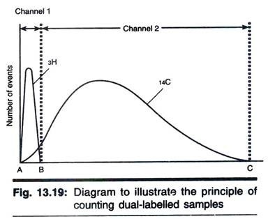
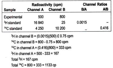
A feature of scintillation counting is that the size of electric pulse produced by the conversion of light energy in the photomultiplier is related directly to the energy of the original radioactive event. Since different β-emitting isotopes have different energy spectra; it is possible to quantify two isotopes separately in a single sample, provided their energy spectra are sufficiently different. Examples of pairs of isotopes that have sufficiently different energy spectra are 3H and 14C, 3H and 35S, 3H and 32P, 14C and 32P, 35S and 32P.
The principle of the method is illustrated with the example of a pair of 3H and 14C as follows:
Most modern counters operate with a so-called multichannel analyzer. These are based on an analogue-to-digital converter; electronic signals from the photomultiplier are converted to digital signals stored in computer. Thus the entire energy spectrum is analyzed simultaneously. This greatly facilitates multi-isotope counting and in particular allows the effect of quenching on dual-label counting to be assessed adequately. Dual-label counting has proved to be useful in many aspects of molecular biology (e.g., nucleic acid hybridization and transcription), metabolism (e.g., steroid synthesis) and drug development.
Determination of Counting Efficiency:
As outlined above, a major problem encountered in scintillation counting is that of quenching, which makes it necessary to determine the counting efficiency of some, if not all, of the samples in a particular experiment. This can be done by one of several methods of standardization, all of which apply to both solid and liquid scintillation counting, though again in this section emphasis is placed on the latter method.
Internal standardization:
The sample is counted (and gives a reading, say, A c.p.m.), removed from the counter and a small amount of standard material of known disintegrations per minute (B d.p.m.) is added. The sample is then re-countered (C c.p.m.) and the counting efficiency of the sample calculated;
counting efficiency = [100 (C – A)/B]%
It is obviously necessary in this method to use an internal standard (the spike) that contains the same isotope as the one being counted and also to ensure that the standard itself does not act as a quenching agent. Suitable 14C-labelled standards include [14C] toluene, [14C] hexadecane, [3H] benzoic acid and 3H2O (benzoic acid and water are themselves quenching agents and must be used in only very small amounts).
Internal standardization is simple and reliable and corrects adequately for all types of quenching. Carefully carried out, it is the most accurate way of correcting for quenching. On the other hand, it demands very accurate pipetting when the standard is added, and it is time consuming because each sample must be counted twice.
It also means that the sample cannot be recounted in the event of error because it will be contaminated with the standard. Moreover, time elapses between the first and second count and changes in sample quenching characteristics can also occur, which can lead to considerable inaccuracies.
However, it is the means by which the following two methods are calibrated:
1. Channels ratio:
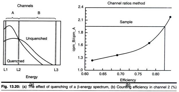
When a sample in a scintillation counter is quenched, the scintillation process is less efficient; less light s produced for a given quantum energy of radiation. Thus the energy spectrum for a quenched sample appears to be lower than that for an unquenched sample (Fig. 13.20a). The higher the degree of quenching, the more pronounced is the resulting decrease in the spectrum.
This fact is applied in the channels ratio method for determining counter efficiency. The method involves the preparation of a calibration curve based on counting in two channels that cover different, but overlapping, parts of the spectrum. As a sample is quenched, and the spectrum shifts to gradually lower apparent energies, the ratio of counts in each channel can easily be determined.
The efficiency is then plotted against channels ratio to form the standard curve (Fig. 13.20b). It is important to realize that a standard curve applies to only one set of circumstances—one radioisotope, counter and scintillation fluid.
Once the standard curve has been prepared, the efficiency of counting experimental samples can be determined. Samples are counted in the same two channels; the ratio is calculated, put into graph and the efficiency read. In practice all the data can be stored in the counter’s computer and corrected values are printed automatically.
Multichannel scintillation counters operate on the same principle but the whole shape and position of the spectrum is analyzed. This is given a digital parameter that relates to counting efficiency. Manufacturers have developed their own title for such parameters, for example LKB Instruments’ Automatic Quench Compensation or Packard’s Automatic Efficiency Control.
These systems have greater precision than the two-channels approach, as the whole of the spectrum is used for analysis. The channels ratio method is suitable for all types and even high degrees of quenching. Furthermore, counting in more than one channel is simultaneous and this method is, therefore, less time consuming than either internal or external standardization.
It is also, in practice, an acceptably accurate method for determining counting efficiency, provided care is taken in the preparation of the calibration curve. However, it is notoriously inaccurate at low count rates, because the error on the counts per minute is high and there will be a larger error on the channels ratio because it is calculated from two values of the counts per minute. It is also inaccurate for very highly quenched samples. For these reasons the method that follows is most frequently the procedure of choice.
2. External standardization:
Instruments have a y-emitting external standard build into the counter. Under the control of the counter each sample to be counted is exposed to this external source, which is automatically shifted from a lead shield to the counting chamber. The y-radiation penetrates the vial and excites the scintillation fluid.
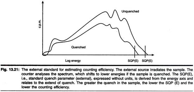
The resulting spectrum is unique to the source and is significantly different from that produced by the sample in the vial. The у-source used (e.g., 137Cs, 133Ba or 226Ra) varies according to the make of the instrument. The spectrum obtained by 226Ra is shown in Fig. 13.21.
Quenching agents present in scintillation fluid will significantly affect the spectrum obtained. The instrument analyses this spectrum and assigns a quench parameter to it. The precise method used depends on the make of counter; LKB. Instruments refer to a standard quench parameter for the external source (SQP(E)) based on a point on the energy axis (Fig. 13.21).
Other manufacturers use slightly different approaches but the principle is same. The spectrum for the external standard varies according to the degree of quench to the vial and, therefore, the efficiency of the counting of the internal experimental sample.
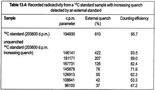
As for the channels ratio method, a standard curve is required, i.e., a range of quench standards is counted and the external spectrum analyzed in each case. The resulting data is used to prepare a standard curve that is held in instrument’s computer. Unknown samples are then counted in the same way, the efficiency read from the standard curve and the sample counts correct.
The external standard approach is now routine in most laboratories, the main advantage over the channels ratio method being that it is suited to samples with low count rates. However, it is not without disadvantages. A standard curve is required for each set of circumstances (as with the channels ratio) and the user can be lulled into a false sense of security.
The system is so highly automated that it is easy to lose the sight of the basic principle and the method is not always appropriate. A case in point is the counting of ‘H precipitated on to filters counted in scintillation fluid. The external standard method will calculate the degree of quench in the fluid (which will probably be very low) but will not take into account the poor preparation of 3H β-particles from the filter into the scintillation fluid; artificially high efficiencies will be recorded. In all cases where an automated procedure for calculating counting efficiencies is employed it is prudent to count a few prepared samples in which the true amount of radioactivity is known.
Sample Preparation:
It is impossible here to give details of all aspects of sample preparation for scintillation counting. Major considerations are outlined.
In solid scintillation counting, sample preparation is easy and only involves transferring the sample to a glass or plastic vial (or tube) compatible with the counter. In liquid scintillation counting, sample preparation is more complex and starts with the decision on that type of the sample vial to be used. These may be glass, low potassium glass (with low levels of 40K that reduce background count) or polyethylene.
The last of these types are cheaper but are not suitable for cleaning and reuse, whereas glass vials can be reused many times provided they are thoroughly cleaned. Polyethylene bottles give better light transfer and result in slightly higher counting efficiencies, but are inclined to exhibit more phosphorescence than do glass vials.
The recent trend is towards mini-vials, which use far smaller volumes of expensive scintillation cocktails. Modern counters are able to accept many types of vial; the smallest vial possible should be used (within the obvious constraints of sample volume) to save costs and in consideration of environmental issues, as scintillation fluids are toxic.
Some counters are designed to accept very small sample in special polythene bags split into an array of many compartments; these are particularly useful to, for example, the pharmaceutical industry where there are laboratories that do large numbers of receptor building assay.
Now we will consider scintillation cocktails employed for counting. Toluene-based cocktails are the most efficient, but will not accept aqueous samples, because toluene and water are immiscible and massive quenching results. Cocktails based on 1, 4-dioxane and naphthalene that can accommodate up to 20% (v/v) water can be used, but they have largely been phased out due to toxicity. Emulsifier- based cocktails are the most frequently used for counting aqueous samples.
They contain an emulsifier such as Triton X-100 and can accept up to 50 % water (v/v); however, phase transitions occur from single phase to two phase gel, as the water content increases. Accurate counting cannot be done it the samples are in two-phase state. Many ready-made cocktails are on the market and are sold with precise instructions regarding sample conditions.
It should be noted that the efficiency of scintillation counting varies with sample volume, though this is less of a problem in modern counters. Nevertheless, care should be taken that sample vials in a given series of counts contain the same volume of sample and that all instruments calibration is done using the same volume as for experimental samples.
If colour quenching is a problem it is possible to bleach samples before counting. Care should be taken, however, since bleaching agents such as hydrogen peroxide can give rise to chemiluminescence in some scintillation cocktails.
Solid samples, such as plant and animal tissues, may be best counted after solubilisation by quaternary amines such as NCS solubilisers or Soluene. Not surprisingly these solutions are highly toxic and great care is required. The sample is added to the counting vial containing a small amount of solubiliser and digestion is allowed to proceed. When digestion is complete, scintillation cocktail is added and the sample is counted. Again, chemiluminescence can be a problem with tissue solubilisers.
A suitable alternative to bleaching of coloured samples or digestion of tissues is the use of combustion techniques. Here sample are combusted in an atmosphere of oxygen, usually in a commercially available combustion apparatus. Thus samples containing 14C would be combusted to 14CO2, which is collected in a trapping agent such as sodium hydroxide and then counted; 3H- containing samples are converted to 3H2O for counting.
As indicated earlier, only important considerations in sample are discussed above and details are not given. However, it is worthy of comment that almost any type of radioactive sample containing β-emitting isotopes can be prepared for counting in a liquid scintillation counter by one method or another, including cuttings from paper chromatographs or membrane filters, again illustrating the versatility and importance of this technique for quantifying radioactivity.
Cerenkov counting:
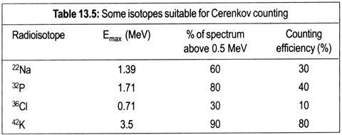
The Cerenkov Effect occurs when a particle passes through a substance with a speed higher than that of light passing through the same substance. If a β-emitter has a decay energy in excess of 0.5 MeV, then this causes water to emit a bluish white light usually referred to as Cerenkov light. It is possible to detect this light using a typical liquid scintillation counter.
Since there is no requirement for organic solvents and fluors, this technique is relatively cheap, sample preparation is very easy, and there is no problem in chemical quenching. Table 13.5 lists some isotopes that are suitable for this detection method. Most work has been done on 32P, which has 80% of its energy spectrum above the Cerenkov threshold and which can be detected at around 40% efficiency. It may be noted from Table 13.5 that, as the proportion of the energy spectrum above 0.5 MeV increases, so too does the detection efficiency.
Scintillation proximity assay:
Scintillation proximity assay (SPA) is an application of scintillation counting that facilitates automation and rapid throughput (if experiments. It is, therefore, highly suited to work such as screening for biological activity in new drugs. SPA beads are constructed from polystyrene (or sometimes other materials) that combine a binding site for a molecule of interest with a scintillation.
You need to remember that some types of radiation do not travel far, in particular β-particles from weak energy emitters such as 3H and 14C. If molecules containing such radioisotopes are in solution with a suspension of SPA beads, the radiation does not stimulate the scintillation in the beads and cannot be detected efficiently by a scintillation counter.
This is because the radiation is absorbed by the solution; it does not reach the scintillant. If, on the other hand, the radioisotope becomes bound to the bead, it is close enough to stimulate the scintillant in the bead, so light is given out and the isotope is detected.
There are many applications of this technology such as enzyme assays and receptor binding, indeed any situation where we want to investigate the interaction between two molecules. Take receptor binding as an example. In this case a receptor for a particular ligand (such as a drug or hormone) is attached to the SPA beads. The ligand is radiolabelled and mixed with the beads.
Any ligand that binds will stimulate the scintillation and be counted, if the researcher wishes to investigate chemicals that might interface with this binding (which is the mode of action of many medicines), that can be added at increasing concentration to study the effect and, for example, determine optimum dosage.
Advantages of scintillation proximity assay are:
1. Versatile: use with enzyme assays, receptors, any molecular interactions
2. Works with a range of appropriate isotopes as 3H, 14C, 35S and 33P
3. No need for separation step (e.g., free from bound ligand)
4. Less manipulation, therefore, reduced toxicity
5. Amenable to automation.
3. Methods Based Upon Exposure of Photographic Emulsions:
Ionizing radiation acts upon a photographic emulsion to produce a latent image much as does visible light. For a photograph, a radiation source, an object to be imaged and a photographic emulsion are required. For an autoradiograph, a radiation source (i.e. radioactivity) emanating from within the material to be imaged (the object) is required, along with a sensitive emulsion. The emulsion consists of a large number of silver halide crystal embedded in a solid phase such as gelatin.
As energy from the radioactive material is dissipated in the emulsion, the silver halide becomes negatively charged and is reduced to metallic silver, thus forming a particular latent image. Photographic developers are designed to show these silver grains as a blackening of the film, and the fixers remove any remaining silver halide. Thus a permanent image of the location of the original radioactive event remains.
This process, which is known as autoradiography, is very sensitive and has been used in a wide variety of biological experiments. These unusually involve a requirement to locate the distribution of radioactivity in biological specimens of different types. For instance, the sites of localization of radiolabelled drug throughout the body of an experimental animal can be determined by placing whole-body sections of the animal in close contact with a sensitive emulsion such as an X-ray plate.
After a period of exposure, the plate, upon development, will show an image of the section in tissues and organs in which radioactivity was present. Similarly, radioactive metabolites isolated and separated by chromatographic or electrophoretic techniques during metabolites studies can be located on the chromatograph and electrophoretograph and the radioactive spots can subsequently be recovered for counting and identification. The technique of autoradiography has become more important with recent developments in molecular biology.
Consequently, more detail is given below on some important aspects of the technique:
Suitable Isotopes:
In general, weak β-emitting isotopes (e.g., 3H, 14C and 35S) are most suitable for autoradiography, particularly for cell and tissue localization experiments. This is because, as a result of the low energy of the negatrons, the ionizing track of the isotope will be short and a discrete image will result. This is particularly important when radioactivity associated with subcellular organelles is being located.
For this 3H is the best radioisotope, since its energy will all be quickly dissipated within the emulsion. Electron microscopy can then be used to locate the image in the developed film. For location within whole organisms or tissues, either 14C or 3H is suitable; more energetic isotopes (e.g., 32P) are less suitable because their higher energy negatrons produce much longer track lengths and result in less discrete images that are not sufficiently discriminatory for microscopic location.
Conversely, for location of, for example, DN A bands in an electrophoretic gel, 32P is useful. In this case low energy H negatrons would largely dissipate their energy within the gel (and in the wrapping around the gel, which is usually necessary to prevent the gel sticking to the emulsion), thereby reducing sensitivity to low level.
However, the more energetic 32P negatrons will leave the gel and produce a strong image. If very thin gels are prepared, then or 14C can be detected with high resolution, for example, DNA sequencing gels where 35S is used as the label.
Choice of Emulsion and Film:
A variety of emulsions is available with different pacing densities of the silver halide crystals. Care must be taken to choose an emulsion suitable for the purposes of experiment, since the sensitivity of the emulsion will affect the resolution obtained. Manufacturers’ literature should be consulted and their advice sought if one is in any doubt.
X-ray film is generally for macroscopic samples such as whole-body sections of small mammals, chromatographs or electrphoretographs. When light or electron microscopic detection of the location of the image in the emulsion is required (cellular and subcellular localization of radioactivity), very sensitive films are necessary, as is a very close apposition of sample and film. In these cases a stripping film technique can be used in which the film is supplied attached to a support.
It is stripped from this and applied directly to the sample. Alternatively, liquid emulsions are prepared by melting strips of emulsion by heating them to around 60°C. Then either the emulsion is poured onto the sample or the sample attached to a support is dipped into the emulsion. The emulsion is then allowed to set before being dried. Such a method is often referred to as a dipping-film method and is preferred when very thin films are required.
Background:
Accidental exposure to light, chemicals in the sample, natural background radioactivity (particularly 40K in glass) and even pressure applied during handling and storage of film will cause a background fog (i.e., latent image) on the developed film. This can be problematic, in high resolution work (e.g., involving microscopy) and care must be taken at all times to minimize its effect. Background will always increase during exposure time, which should, therefore, always be kept to a minimum.
Time of Exposure and Film Processing:
The time of exposure depends upon the isotope, sample type, level of activity, film type and purpose of the experiment. The same applies to the processing of the film in order to display the image. Generally the process must be adapted to a given purpose, and a great deal of trial and error is often involved in arriving at the most suitable procedures.
Direct Autoradiograph:
In direct autoradiography, the X-ray film or emulsion is placed as close as possible to the sample and exposed at any convenient temperature. Quantitative images are produced until saturation is reached. The approach provides high resolution but limited sensitivity; isotopes of energy equal to or higher than 14C (Emax = 0.156 MeV) are required.
Fluorography:
Many of the currently popular methods in molecular biology involve separation of macromolecules or fractions of macromolecules by gel electrophoresis. The separated macromolecules or fractions from bands in the electrophoretograph that must be located. This is often achieved by radiolabelling the macromolecules with 3H or 14C and subjecting the gel to autoradiography.
Because these are weak β-emitters, much of their energy is lost in the gel and long exposure times are necessary even when very high specific activity source are used. However, if a fluor (e.g., PPO or sodium silicate) is infiltrated into the gel, and the gel dried and then placed in contact with a pre-flashed film, sensitivity can be increased by several orders of magnitude.
This is because the negatrons emitted from the isotope will cause the fluor to become excited and emit light, which will react with the film. Thus use is made of both the ionising and the excited effects of radioactivity in fluorography.
Intensifying Screens:
When 32P-labelled or y-isotope-labelled samples (e.g., [32P] DNA or 128I-labelled protein fractions in gels) are to be located, the opposite problem to that presented by low energy isotopes prevails. These much more penetrating particles and rays cause little reaction with the film as they penetrate right through it, producing a poor image.
The image can be greatly improved by placing, on the other side of the film from the sample, a thick intensifying screen consisting of a solid phosphor. Negatrons penetrating the film cause the phosphor to fluoresce and emit light, which superimposes its image on the film. There is, therefore, an increase in sensitivity but a parallel reduction in resolution due to the spread of light emanating from the screen.
Low Temperature Exposure:
If the energy of ionizing radiation is converted to light (i.e., with fluorography or intensifying screens) the kinetics of the film’s response are affected. The light is of low intensity and a back reaction occurs that cancels the forming of latent image. Exposure at low temperature (—700C) slows this back reaction and will, therefore, provide higher sensitivity. There is no point in doing direct autoradiography at low temperature as the kinetics of the film response are different. There is nothing to be gained by exposing pre-flashed film at low temperature.
Pre-flashing:
As described above, the response of a photographic emulsion to radiation is not linear and usually involves a slow initial phase (lag) followed by a linear phase. Sensitivity of the phase may be increased by pre-flashing. This involves a millisecond light flash prior to the sample being brought into juxtaposition with the film and is often used where high sensitivity is required or it results are to be quantified.
Quantification:
Autoradiography is usually used to locate rather than to quantify radioactivity. However, it is possible to obtain quantitative data directly from autoradiographs by using a densitometer, which records the intensity of the image. This in turn is related to the amount of radioactivity in the original sample. There are many varieties of densitometers available and the choice made will depend on the purpose of the experiment.
Quantification is not reliable at low or high levels of exposure because of the lag phase (i.e., the back reaction, as described above) or saturation, respectively; however, pre-flashing combined with fluorography or intensifying screens obviates the problem for small amount of radioactivity. In this case all photons contribute equally to the image of the pre-exposed film.

