A project report on waste water treatment. This project report will help you to learn about: 1. Introduction to Waste Water Treatment 2. Basic Parameters in Waste Water Characterisation 3. Biochemical Characteristics 4. Stages 5. Domestic Waste Water Treatment 6. Wastewater Discharged 7. Chemical Specifications 8. Classification of Treatment Methods for Industrial Waste.
Contents:
- Project Report on Introduction to Waste Water Treatment
- Project Report on Basic Parameters in Waste Water Characterisation
- Project Report on the Biochemical Characteristics of Waste Water Treatment
- Project Report on the Stages of Waste Water Treatment
- Project Report on Domestic Waste Water Treatment
- Project Report on Wastewater Discharged
- Project Report on the Chemical Specifications of Waste Water Treatment
- Project Report on the Classification of Treatment Methods for Industrial Waste
Contents
- Project Report # 1. Introduction to Waste Water Treatment:
- Project Report # 2. Basic Parameters in Waste Water Characterisation:
- Project Report # 3. Biochemical Characteristics of Waste Water Treatment:
- Project Report # 4. Stages of Waste Water Treatment:
- Project Report # 6. Wastewater Discharged:
- Project Report # 7. Chemical Specifications of Waste Water Treatment:
- Project Report # 8. Classification of Treatment Methods for Industrial Waste:
Project Report # 1. Introduction to Waste Water Treatment:
The composition of municipal waste water varies from place to place. Sometimes industrial wastes also mix with sewage. The type of treatment of waste water thus depends upon its characteristics and the desired quality of water after treatment.
The purpose of waste water treatment is to remove/reduce organic and inorganic substances, nutrients toxic substances kill pathogenic organisms etc. so that the quality of discharged water is improved to meet the permissible level of water to be discharged in some water body, on land or agricultural field.
Treatment of water thus aims at reduction of BOD, COD, eutrophication, etc. of receiving water bodies and prevention of bio-magnification of toxic substances in food chain and prevention of disease due to pathogenic organisms present in the waste water.
Project Report # 2. Basic Parameters in Waste Water Characterisation:
i. Sources information:
Sources information for the individual points of origin waste components, individually or at least by classes, rate of discharge during production run (average and maximum). Periodic discharges due to batch operation. Duration and frequency of production runs. Susceptibility to emergency discharges or spills.
ii. Chemical Composition:
Organic and inorganic components, by compounds or classes.
Gross organics: Chemical Oxygen Demand (COD), Total Organic Carbon (TOC), Biochemical Oxygen Demand (BOD), extractable.
Specific problems ions (As, Ba, Cd, Cr, CN, Hg, Pb, Se, Ag, NO3)
Specific problem organics, e.g. phenol, certain pesticides, benzidine, polychlorinated bio-phenyls, certain poly-nuclear aromatics.
Total dissolved salts
pH, acidity, alkalinity
Nitrogen and phosphorus.
Oils and greases (extractables)
Oxidizing or reducing agents (.e.g., sulphides) Surfactants
Chlorine demand.
iii. Biological Effects:
Biochemical oxygen demand
Toxicity (aquatic life, bacteria, mammals, plants) Pathogenic bacteria.
iv. Physical Properties:
Temperature range and distribution
Insoluble components: colloidal, settleable, floatable
Colour
Order
Foam ability
Corrosiveness.
v. Flow Data for Total Discharge:
Average daily flow rate
Duration and level of maximum flow rate
Maximum rate of change of flow rate.
Project Report # 3. Biochemical Characteristics of Waste Water Treatment:
Suspended solids are determined by filtering suitable aliquot of sample through a previously weighed sintered grooch crucible and drying the crucible in an oven at 103° – 105°C to constant weigh. The difference in the initial and final weight of the curcible gives SS content, mg/1.
i. Settleable Solids:
Allowing 1 litre of the sample to settle for about 1 hr at 20°C in an 1 ra cone. The volume of settleable matter in the tapered conical tube is recorded as ml/1. The settleable solids may be expressed in mg/1 also.
Total solids:
Determined by evaporating a known volume of the waste water sample and drying the residue for 24 hrs. in oven at 103°-105°C. Followed by weighing. This gives the total solids content of the sample which comprises the dissolved as well as suspended solids.
Filterable solid. — Organic and Inorganic Solid.
Dissolved oxygen:
The D.O. content of a water sample is measured codes metrically by the modified Wrinkler’s method.
Oxygen present in the sample oxidize in divalent mass generation its higher valency with precipitates as a brown hydrates, oxides after addition of NaOH and KI upon acidification manganese reverts to divalent state and liberate iodine from KI equivalent to DO content of the sample which is titrated against 1 standard N/80 solution of sodium thiosulphate using starch as an indicator.
Interference due to nitrate can be eliminated by adding sodium azide to the alkelene potassium iodide solution.
The D.O. is usually expressed as mg/1 or ppm.
This is measured by D.O. oxy-meter
ii. Biochemical Oxygen Demand (B.O.D.):
Theory:
Micro-organisms can utilize organic substance as food and oxides them to obtain energy for their life process. Some bacteria are also capable to utilize, reduce inorganic substance such as Fe2+, S2-and NH3 to obtain energy.
In the biological degradation of sewage and other wastes (caused by various types of living organisms or bacteria) organic matter is converted into fragments consisting of acetic acid. When sufficient oxygen is present such as in aerobic system. Oxygen is reduced while the organic matter is oxidised into CO2 and water.
When sufficient amount of oxygen is not available i.e., anoxic conditions prevail, organic matter is oxidised by using nitrate as an electron acceptor.
When oxygen is absent i.e., anaerobic conditions exist SO42– , PO43–and CO2 whatever available acts as electron acceptor and get reduced to H2S, HS– (Mercaptons-rotten eggs smell), PH3, CH4.
The amount of oxygen required by a mixed population of micro-organisms on oxidising organic matter present in a sample, under strictly aerobic conditions, is generally known as B.O.D., and is directly related to the extent of pollution (by sewage or other oxygen- demanding wastes).
The rate of bacterial oxidation at any instant is proportional to the amount of the oxygen-demanding waste left at the instant, i.e., this reaction follows first order reaction and theoretically will be completed in infinite time.
However, it has been observed that about 70 – 80% of the total B.O.D. is exerted in first 5 days. The sample is therefore incubated for 5 days at 20°C and the B.O.D. values determined are reported as B.O.D. A polluted sample may consume more oxygen in 5 days than present in water (nearly 9 mg/1 at 20°C). Hence before analysis it is diluted with a specially prepared “Dilution Water”.
The dilution water is prepared by passing air in distilled water for 1 – 2 days so as to make it saturated by dissolved oxygen. In one liter of this 1 ml each of phosphate buffer MgCl2, CaCl2 and FeCl3 are mixed. The sample so diluted is taken in two bottles. The D.O. of one is determined immediately and that of the other after 5 days incubation. The B.O.D. of the sample is then calculated by
where D1= D.O. of the sample in mg/l at the start of the experiment
D2 = D.O. of the sample in mg/1 after 5 days
A = ml of the sample before dilution
B = ml of the sample after dilution.
Measurement of D.O. content of the sample before or after in combustion at 20°C for 5 days or glutonic BOD at 27°C for 3 days. If the sample does not contain any oxygen, it is supplied with oxygen and the depletion caused is calculated as the B.O.D. measurement. Microbial organisms or seed may also have to provided B.O.D. is expressed in mg/1.
iii. Chemical Oxygen Demand (C.O.D.):
The C.O.D. is usually defined as the amount of oxygen used while oxidizing the organic matter content of a sample with a strong chemical oxidant under acidic conditions.
The organic matter in the sample is related as the oxygen required (C.O.D.) in accordance with equation:
In C.O.D. determination the organic matter is completely oxidised to CO2 and H2O, the C.O.D. values are greater than B.O.D. values which represent the amount of oxygen that bacteria require for stabilizing biologically oxidisable matter.
The C.O.D. tests are performed with the same objectives as those of B.O.D. test. C.O.D. test results are obtained in 5 hours whereas B.O.D. results are obtained in 5 days. In comparison to B.O.D., there is least interference in C.O.D. test.
Chemical oxygen demand is the amount of oxygen consumed under specified condition in the oxidation of organic and oxidisable inorganic matter connected for the influence of chlorides.
When the waste water aliquot of the sample is refluxed with a known excess of oxidizing agent potassium dichromate in the 50% sulphuric acid solution in the presence of AgSO4. Silver sulphate as catalyst and mercuric sulphide.
The organic matter of the aliquot sample is oxidized to water, CO2 and ammonia. The excess dichromate remaining unreacted in the solution water standard solution of 0.1 N ferrous ammonium sulphate.
Where V1 and V2 are the volume of ferrous ammonium sulphate run down in the blank and test experiments.
One sample volume of the sample taken for the test.
Project Report # 4. Stages of Waste Water Treatment:
Waste water, whether domestic or industrial have several undesirable components, the organic and inorganic pollutants that are potentially harmful to the environment and human health. The treatment of waste water and its proper management has become a necessity in order to conserve this vital resource.
The main aim of waste water treatment is the removal of contaminants from water so that the treated water can be reused for beneficial purposes. The waste water treatment is carried out in three stages: Primary, Secondary and Tertiary or advanced waste treatment.
i. Primary Treatment:
Waste water, contains a wide variety of solids of various shapes, sizes and densities. The primary treatment is of general nature and is used for removing suspended solids, odour, colour and to neutralize the high or low pH in the case of industrial effluents.
This stage exploits the physical or chemical properties of the contaminants and removes the suspended and floating matter by screening, sedimentation, floatation, filtration, precipitation etc.
(i) Screening:
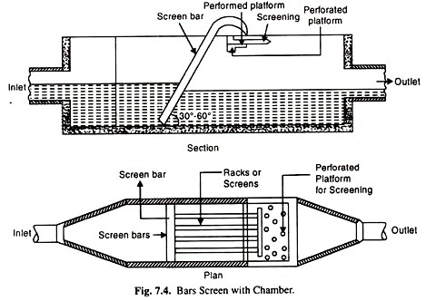
Screening devices are used to remove coarse solids from waste water. Coarse solids consist of sticks, rags, boards and other large objects that often and inexplicably, find their way into waste water collection systems.
Because the primary purpose of screens is to protect pumps and other mechanical equipment and to prevent clogging of valves and other appurtenances in the waste water plant, screening is normally the first operation performed on the incoming waste water.
Waste water screens are classified as coarse or fine, depending on their construction. Coarse screens usually consist of Vertical bars spaced 20-60 mm apart and inclined away from the incoming flow. Solids retained by the bare are usually removed by manual raking in small plants, while mechanically cleaned units are used in larger plants.
Fine screening (10-20 mm) consist of woven-wire cloth or perforated plates mounted on rotating disk or drum partially submerged in the flow, or on travelling belt. Fine screens should be mechanically cleaned on a continual basis.
The quantity of solids removed by screening depends on screen-opening size. Screened solid are coated with organic material of a very objectionable nature and should be promptly disposed-off to prevent a health hazard and/or nuisance condition. Disposal in a sanitary land fill, grinding and returning to the waste water flow, and incineration are the most common disposal practices.
(ii) Comminuting:
As mentioned above screenings are sometimes shredded and returned to the waste water flow. A hammer mill device is most often used for this purpose. Most often; a shredding device called a comminutor is located across the flow path and intercepted the coarse solids and shreds them to approx. 0.8 mm in size. These solids remain in the waste water.
Many kinds of comminutes are available. Basic parts include a screen and cutting teeth. The screen may be a slotted drum that rotates in the vertical plane. Stationary teeth then shred material that is intercepted by the screen.
Other types use as stationary semi-circular screen and rotating or oscillating cutting teeth. Another device, called a barminutor, uses a vertical bars screen with a cutting head that travels up and down, the rack of bars, shredding the intercepted material.
Shredding devices should be located ahead of pumping facilities at the treatment plant. Grit removal ahead of the shredder will save wear on the cutting head. Usually, however, grit chambers are located at or above ground level to facilitate grit handling, and pumps may be necessary to lift the sewage to them. In this case, shredding is done ahead of the pumps and cutter wear must be tolerated.
(iii) Grit Removal:
Municipal waste water contains a wide assortment of inorganic solids such as pebbles, sand, silt, egg shells, glass and metal fragments. Operations to remove these inorganics will also remove some of the larger, heavier organics such as bone chips, seeds etc. Together, these comprise the material known as grit in waste water treatment systems.
Most of the substances in grit are abrasive in nature and will cause accelerated wear on pumps and sludge handling equipment with which it comes in contact. Grit deposits in areas of low hydraulic shear in pipes, sumps and clarifiers may absorb greases and solidify.
Also, these materials are not biodegradable and occupy valuable space in sludge digesters. It is therefore, desirable to separate them from the organic suspended solids.
The latter should not be allowed to settle along-with, otherwise it gets entangled with the inorganic matter causing septicity of waste water and requiring unnecessary labour and expenses for removal. A velocity of flow between 0.15 to 0.3 m/sec is practically considered sufficient for this purpose.
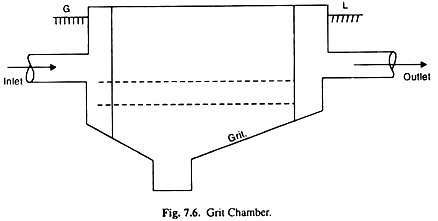
Grit removal facilities basically consist of an enlarged channel area where reduced flow velocities allow grit to settle out. Many configurations of grit tanks are available. At-least two separate chambers should be provided, one to take care of low flow and the other for the high flow. A period of detention of 1 minute is commonly employed. Grit chambers are cleaned by hand, mechanically or hydraulically.
Hand clearing is done only in the case of smaller plants, is less hygienic and odour free though somewhat easier for disposing of the removed material than in the case of mechanical cleaning. In hydraulic-cleaning, the deposited material is flushed out under fire-streams directed from a central point and removed through pipes in the side-walls or bottom of the chamber.
(iv) Skimming Tanks:
A skimming tank is a chamber so arranged that the floating matter like oil, fat, grease etc., rise and remain on the surface of the waste water (Sewage) until removed, while the liquid flows out continuously under partitions or baffles.
It is necessary to remove the floating matter from sewage otherwise it may appear in the form of unsightly scum on the surface of the settling tanks or interfere with the activated sludge process of sewage treatment. It is mostly present in the industrial sewage. In ordinary sanitary sewage, its amount is usually too small.
The chamber is a long trough shaped structure divided up into two or three lateral compartments by vertical baffle walls having slots for a short distance below the sewage surface and permitting oil and grease to escape into stilling compartments.
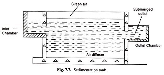
The rise of floating matter is brought about by the blowing air into the sewage from diffusers placed in the bottom. Sewage enters the tank from one end. A theoretical detention period of 3 minutes is enough.
The floating matter can be either hand or mechanically removed. Grease traps are in reality small skimming tanks designed with submerged inlet and bottom outlet.
The traps must have sufficient capacity to permit the sewage to cool and grease to separate. Frequent cleaning through removable covers is essential for satisfactory operation. Grease traps are commonly employed in case of industries, garages, hotels, and hospitals.
(v) Sedimentation:
In this step, the settleable solid are removed by gravitational settling under quiescent conditions. The sludge formed at the bottom of the tank is removed as under flow either by vacuum suction or by raking it to a discharge point at the bottom of the tank for withdrawal. The clear liquid produced is known as the overflow and it should contain no readily settle- able matter.
The sedimentation operation in waste treatment applications may be carried out in rectangular horizontal flow, circular radial flow or vertical flow basis. Fig. 7.8 shows the three main types of arrangements.
In rectangular tanks, feed is introduced at one end along with the width of the tank and the overflow is collected at the surfaces, either across the other end or at different point along the length of the tank. An endless conveyor scrapes the floating material into a screen through which it also pushes the settled solids into a sludge hopper.
(vi) Flotation:
Flotation may be used in place of sedimentation, primarily for treating industrial waste water containing finely divided suspended solids and oily matter. Flotation technique is used in paper industry to recover fine fibres from the screened effluent and in the oil industry for the classification of oil bearing waste. It is also used for treating effluents from tanneries, metal finishing, cold-rolling and pharmaceutical industries.
Particles of density very close to that of water are very difficult to settle in normal sedimentation tanks and take a long time for separation. In such cases, the separation can be speeded up by aerating the effluent where by air bubbles are attached to the suspended matter.
This has the effect for increasing the buoyancy of the particles as a result; the particles float to surface from where they can be readily removed. To aid in the flotation process, chemical coagulants such as aluminium and ferric salts or polymer coagulant-aids are often used. These chemicals increase the flocculent structure of the floated particles so that they can easily entrap the air bubbles.
Two methods of flotation are currently available:
(1) Dispersed-air flotation and
(2) Dissolved air flotation.
1. In dispersed air flotation, air is introduced directly into the liquid through a revolving impeller or through diffusers. The air bubbles generated in dispersed air flotation systems are normally about 1 mm in diameter and they usually cause turbulence which breaks up fragile floe particles.
Due to this, dispersed air flotation is not favoured technique in the treatment of municipal wastewater, although it finds a limited application in treating industrial wastes containing oil, grease and fine powders.
2. In dissolved air flotation, air is intimately brought into contact with the waste water at a pressure of several atmospheres when air is dissolved. The pressure on the liquid is reduced to atmospheric level through a backpressure valve, there by releasing micron-sized bubbles.
Suspended solids and oil are carried to the surface of the flotation tank by these minute air bubbles. A typical flotation system is shown in Fig. 7.10. Here, the entire flow is pressurized and held in the retention tank so that the air gets dissolved in the liquid.
The intense mixing of air and waste water in the pressurization system often degrades flocculent suspensions or oil emulsions following chemical treatment. A portion of the clear effluent is recycled for pressurization to prevent such degradations.
Compressed air is introduced into the discharge of the recycle pump and intimate contact is achieved in the retention tank. The recycled flow is then returned through a back pressure valve (where the pressurized air is released and mixed with the influent for flotation. The time in the flotation tank is about half an hour.
(vii) Neutralization:
When pH of the industrial waste is too high or too low then it should be neutralized by acid or alkali and only neutral effluent should be discharged into the drain or public sewer.
For neutralization of the acidic effluent, the following techniques are used:
1. Lime-Stone Treatment:
For acidic effluents, lime stone can be used as it will form calcium compounds depending upon the presence and amount of acid.
2. Caustic Soda Treatment:
Although costly, yet the method is also utilized for neutralizing the acid. Caustic soda is added in the effluent to make the pH neutral. Only small amounts of caustic soda is needed for this work.
For neutralization of alkaline effluent, the following techniques are followed:
(a) Carbon Dioxide Treatment:
If the industry is producing carbon dioxide then only this method should be utilized for neutralizing the pH, otherwise it would be costly affair. Here carbon dioxide is passed in alkaline effluent to make its pH almost 7. (i.e. Neutral value).
(b) Sulphuric Acid Treatment:
This is a common method of neutralising alkaline effluent. Here sulphuric acid is added in the effluent till pH becomes almost 7.
(c) Utilizing Waste Boiler-flue Gas:
The stack gas which contains about 12 percent carbon dioxide is utilized to react alkaline effluent to make it neutral.
ii. Secondary or Biological Treatment:
The biological process of sewage is a secondary treatment involving removing, stabilizing and rendering harmless very fine suspended matter, and solids of the waste water that remain even after the primary treatment has been done.
Since much of the organic material in waste water may be colloidal or dissolved, the primary treatment processes are largely ineffective in removing it. The organic matter still represents a high demand for oxygen which must be reduced further so that the effluent may be rendered suitable for discharge into the water bodies.
In biological treatment, oxygen supplied to the bacteria is consumed under controlled conditions so that most of the B.O.D. is removed in the treatment plant rather than in the water course.
Thus, the principal requirements of a biological waste treatment process are an adequate amount of bacteria that feed on the organic material present in waste water, oxygen and some means of achieving contact between the bacteria and the organics.
Two of the most commonly used systems for biological waste treatment are:
(i) The activated sludge system and
(ii) The biological film system.
In the activated sludge system, the waste water is brought into contact with a diverse group of micro-organisms in the form of a flocculent suspension in an aerated tank, whereas in the biological film system, also known as trickling filters, the waste water is brought into contact with a mixed microbial population in the form of a film of slime attached to the surface of a solid support system. In both cases the organic matter is metabolized to more stable inorganic forms.
(i) Activated Sludge Process:
The essential features of activated sludge process are: an aeration stage, solids-liquid separation following aeration, and a sludge recycle system. Waste water after primary treatment enter and aeration tank where the organic matter is brought into intimate contact with the sludge from the secondary clarifier.
This sludge is heavily laden with micro-organisms which are in an active state of growth. Air is introduced into the tank either in the form of bubbles through diffusers or by surface aerators.
The micro-organisms utilize the oxygen in the air and convert the organic matter into stabilized, low-energy compounds such as NO3, SO4, CO2 and synthesize new bacterial cells.
The effluent from the aeration tank containing the flocculent microbial mass, known as sludge, is separated in a settling tank sometimes called a secondary settler of a clarifier. In the settling tank the separated sludge exits without contact with the organic matter and becomes activated to the aeration tank as a seed; the rest is wasted.
If all the activated sludge is recycled, then the bacterial mass would keep increasing to the stage where the system gets clogged with solids. It is therefore, necessary to ‘waste’ some of the micro-organisms, and this wasted sludge is the one which is processed and disposed of. The process flow diagram for a typical activated sludge plant is given in Fig. 7.11.
(ii) Trickling Filters or Biological Film System:
The secondly commonly used biological waste treatment process is the trickling filter method. Trickling filters are also called percolating filters. It has good adaptability to handle peak shock loads and the ability to function satisfactorily after a short period of time.
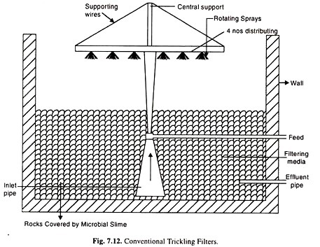
Milk processing, paper mill and pharmaceutical wastes are among those treated by tricking filters. Conventional trickling filters normally consist of a rock bed. 1 to 3 metres in depth, with enough openings between rocks to allow air to circulate easily.
The influent is sprinkled over the bed packing (See Fig. 7.12) which is coated with a biological slime. As the liquid trickles over the packing, oxygen and the dissolved organic matter diffuse into the film to be metabolized by the micro-organism in this slime layer. End products such as NO3, CO2 etc. diffuse back out of the film and appear in the filter effluent.
The other methods are:
(iii) Aerated lagoon
(iv) Oxidation pond
(v) Anaerobic digestions
As the micro-organisms utilize the organic matter, the thickness of the slime film increases to a point where it can no longer be supported on the solid media and gets detached from the surface. This process is known as sloughing. A settling tank following the trickling filter removes the detached bacteria film and some suspended matter.
Handling and disposal of sludge from biological waste water treatment plant is an important problem and represents about half the cost of most sewage treatment plants.
The concentration of solids in the primary sewage sludge is about 5 percent; the activated sludge contains less than 1 percent solids; from trickling filters has about 2 percent solids. The common unit operation of sludge treatment and disposal involve concentration or thickening, digestion, conditioning, dewatering, oxidation and safe disposal.
(iii) Aerated Lagoon:
The aerated lagoon system consists of a large pond that is equipped with machines aerations to maintain an aerobic environment and to prevent settling of the suspend biomass. The population of microorganisms in an aerated lagoon is much lower than that in an actual sludge system because there is no sludge recycle.
(iv) Oxidation Pond:
Photosynthesis organic matter. The CO2 cycle is oxidation plant.
iii. Advanced Waste Water Treatment:
Usually the primary and secondary treatments are sufficient to meet waste water effluent standards. However, if water produced is required to be of higher water quality standards (in case the water to be put to some direct reuse) then advanced waste water treatment is carried out.
A wide variety of methods are used in advanced waste treatment, which includes the removal of:
(a) Suspended solids,
(b) B.O.D.,
(c) Plant nutrients,
(d) Dissolved solids and
(e) Toxic substances.
These methods may be introduced at any stage of the total treatment process as in the case of industrial waste waters or may be used for complete removal of pollutants after the secondary treatment.
The wastewater treatment processes are basically concentrating or thickening processes on which the suspended solids are removed as sludge’s. The impurities in the wastewater are concentrated into solid form and are then separated from the bulk liquid. This concentrated form is referred to as sludge.
Project Report # 5. Domestic Waste Water Treatment:
Conventional sewage treatment plants are based on biological decomposition of nontoxic organic wastes, using bacteria. Such biological decomposition is conducted under aerobic conditions, i.e. in the presence of plenty of oxygen.
For oxidation of 1 mg of carbon, 2.67 mg of dissolved oxygen is required. Organic, hydrogen, sulphur and nitrogen, the major elements in waste water, consume additional oxygen for their oxidation.
The solubility of O2 in water is only 9 ppm (mg/L) at 20°C and less at higher temperature. The purity of water depends on the rate of transport.
Of O2 by aeration and on the total load organic material which requires oxidation. The organic load is expressed in terms of B.O.D. i.e. biochemical oxygen demand which means mg of O2 needed to decompose the organic material in 1L waste water.
As a rough estimate, the B.O.D. values (mg.O2/Litre waste water) for various processes are:
Domestic sewage, 165; industrial waste water, 200; paper industry 372; food industry, 747; metal industry 13. Evidently such a heavy load is likely to upset the capacity of most natural water bodies so that sewage treatment is essential for maintaining the water quality.
Aerobic Treatment Processes:
These are secondary waste treatment methods by biological processes. After primary treatment for removal of insoluble matter i.e. grit, grease, scum etc. and sedimentation, the resulting sludge is subjected to secondary treatment.
The aerobic treatment process the biodegradable organic matter is utilised by the bacterial cells (microorganisms) for their growth and metabolism and in the process huge quantity of cell mass and CO2 are generated. About 50% of biodegradable C present in the waste water is converted into cell mass and the rest into CO2.
Among the available processes, the most important is the Activated Sludge Process. This is shown in Fig. 7.17. It is a continuous flow flocculated growth process in which bacterial floes (activated sludge) are separated from treated effluent by a clarifier and recycled to the aeration tank to maintain a high degree of process intensity.
The microbial cell matter which is formed as part of the waste degradation process is generally kept in the aeration tank till the microorganisms reach their saturation point of growth when the cells flocculate well to form settleable solids.
These solids settle out in a settler and part of it is discarded. The bulk of the solids, return sludge, is recycled to the bottom of the aeration tank and encounters the fresh sewage. The return sludge and the influent sludge provide optimum conditions for rapid degradation of organic matter.
Oxidative degradation is accomplished mostly by chemoheteraoropic bacteria and ciliated protozoa. Effective degradation is caused by predominant gerera like Pseudomonas, Zoogloea, Flavobacterium, Alcallgenes etc.
Nitrification in the Activated Sludge process (ASP) proceeds by the action of the genera Nitrosomona, Nitrospira, etc. in the first step and by Nitrobacter, Nitroseoccus etc. in the second step. Denitrification takes place by the action of the genera Pseudomonas, Microccus etc.
The merits of the ASP are:
(i) Low retention time and
(ii) B.O.D. removal up to 95%.
The demerits of the ASP are:
(i) Low strength waste, B.O.D. 1500-2500 mg/L,
(ii) Energy is required for aeration,
(iii) High sludge production and
(iv) Disposal problem of activated sludge.
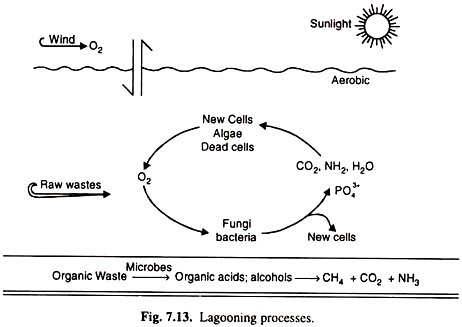
Another process is the lagooning process, the oldest process in the country.
There are several types of this process;
(a) Aerobic lagooning,
(b) Anaerobic lagooning and
(c) Aero- bio-anaerobic lagooning.
Anaerobic Treatment Processes:
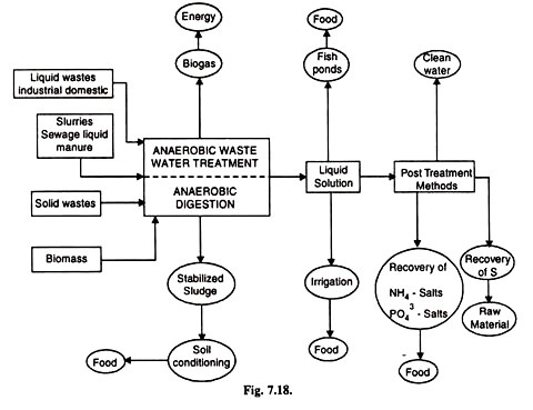
In these processes about 95% of biodegradable C is decomposed into biogas (c.f. 50% in aerobic process) and the rest 5% into biomass. Three main steps are involved in the breakdown of organic waste under anaerobic conditions.
These steps are essentially hydrolysis of biopolymers to monomers, fermentation of monomers to volatile acids and methanogenesis. The anaerobic degradation of carbohydrate takes place as follows; polysaccharide to pyruvate and pyruvate to lactic acid or ethanol.
The microbial species responsible for anaerobic degradation are: Actinomyces, Arthrobacter, Cirobacter, Escherichia, lactobacillus, Micrococcus etc. Anaerobic treatment is illustrated in the flow-sheet Fig. 7.18.
Ion Exchange:
This technique is used extensively for concentration and separation of metal ion from large volumes of natural and waste waters. The total free metal ion content of a water sample is determined by passing the sample through H+ – cation exchanges and titrating the acid liberated with a standard alkali solution. Another aliquot may be titrated with EDTA to estimate the total hardness of water.
Ion exchange chromatography provides an excellent method for concentration and separation of ions from waste water. The ions are first concentrated on a suitable ion exchange column and then selectively eluted to be measured polarograhically, spectrophotometrically, radio metrically etc. Ion exchange membranes are also useful for separation and concentration of metal ions prior to analysis.
Aerobic:
1. It is accomplished in the presence of aerobic bacteria flourished in the presence of free dissolved oxygen.
2. Aerobic bacteria consume organic matter for their food and thereby oxidizing to stable the products.
3. Stable end products are nitrates, CO2, sulphur.
4. Needs large area.
5. Commissioning and maintenance are expensive.
Anaerobic:
1. It is accomplished in the presence of anaerobic bacteria flourished in the absence of free dissolved oxygen.
2. Anaerobic bacteria survive by utilizing the bounded molecular OX2 in NO3 & SO4.
3. NH3, N. Hydrogen sulphide methane are produced, which give abnoxious odours.
4. No large areas needed.
5. Maintenance easy and cheap.
Anaerobic treatments a sludge digestors septic tank – Convention anaerobic digestors.
High two stage anerobic sludge digestors.
Project Report # 6. Wastewater Discharged:
1. Cyanide 1 PPM
Organic Phosphorous 1 PPM
Cadmium 2PPM
Lead 1PPM
Chromium hexa valance 0.5 PPM,
Arsenic 0.5 PPM
2. Effluent to coastal water 5-9 pH
Effluent to other water 5.8-8.6 pH
3. Chemical oxygen demand 120-250 mg/1.
4. Biochemical oxygen demand at 20°C 120-160 mg/litre
5. Suspended solids 150-160 mg/1
In to inland surface water 100
on land for irrigation 200
6. Colitis germ groups 3000 m pn/cm2
7. Mineral of 5 PPM
8. Vegetable oil and fats 30 PPM Oil and grease 20mg/l
9. Phenols 5 PPM
10. Zinc 5 PPM
11. Soluble iron 10 PPM
12. Soluble magnese 10 PPM
13. Total chromium 2 PPM
14. Fluorine 15 PPM
15. Particle size of suspended solids shall pass 850 micron IS sieve
16. Dissolved solids inorganic 200 mg/l
17. Temperature 40°C.
Project Report # 7. Chemical Specifications of Waste Water Treatment:
Identification of inorganic organ metallic or organic species of an element/chemical in the environment.
Arsenic:
Acetate arsenic poisoning can arise from the indigestion of as little as 100 mg As. Copper. This is one of the essential elements for human. The adult daily requirement is about 2 mg.
Zinc:
This is an essential and beneficial element for human body.
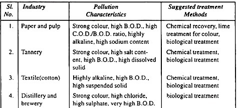
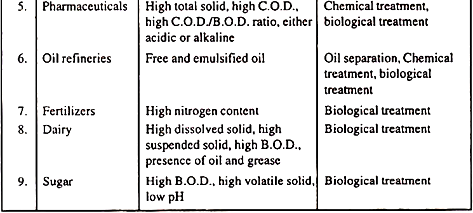
Pollution Characteristics of different Industries:
Project Report # 8. Classification of Treatment Methods for Industrial Waste:
Treating the waste is first step of processing of the waste when it comes directly from the industry. Waste is observed as three states of matter as solid, liquid and gas; then its treatment is decided.
Mainly three types of treatment is done:
(i) Physical treatment.
(ii) Chemical treatment.
(iii) Biological Treatment.
(i) Physical treatment:
Physical treatment can be defined as a process or processes where by undesirable constituents of an effluent are removed by separation like suspended solids, dissolved solids or liquids.
(ii) Chemical Treatment:
Portion of waste which contains harmful chemicals is treated chemically so that it can be disposed without harm.
Like acid and alkalies are neutralized before being oxidation and reduction of ions and electrolysis etc.
Physical Treatment:
1. Introduction:
Physical treatment can be defined as a process or processes where by undesirable constituents of an effluent are removed by separation. Those constituents that need to be removed may be suspended solids, dissolved solids, or liquids other than the normal bulk phase of the effluent which is in most instances is water.
Removal of suspended solids and contaminating liquids is mainly by two processes:
(a) Settlement
(b) Flotation
2. Processes Plant:
(a) Settlement:
The principle on which this works is the matter to be separated should have higher specific gravity than the phase in which it is dispersed. Chemical addition is done to increase the specific gravity. Plants used for these are described below:
(b) Horizontal flow tanks:
This is most popular and oldest method. The initial plants simply consisted of a rectangular or square tank where effluent entered at one end and the clarified effluent has been discharged at the other end with the suspended solids settling out as a sludge at the bottom.
A modern amendment has baffles to make settling time more and sinusoidal motion of flow. One drawback is poor distribution of effluent inlet is weir or number of penstock weir.
(c) Radial Flow Tank:
These are circular in plan, with either flat or gently sloping floors. The scraper mechanisms of circular tanks are comparatively simple, but performance is not being equal to horizontal flow tank.
As with many settlement plant, uniform distribution is needed so that the full volume of tank is needed for the liquid solid separation process. One advantage of this type of plant is that, due to the large discharge area normally used, gentle flow occurs through the plant, provided of course no short circuiting occurs.
(d) Upward-Flow Clariflers:
The principle of operation of this type of clarifier is that freshly flocculated water or effluent come into contact with previously formed particles which have been optimised in size. Consequently collision occur between these particles causing induced flocculation of the freshly treated water.
In this way size of particles is increased, improving rates of sedimentation. A plant to be designed for an effluent or water having a consistent suspended solids content and flow velocity. Sludge is usually continuously removed to maintain the blanket consistency. This type of plant is often called a sludge contact clariflre. It has very reduced free surface area.
