This article throws light upon the eight most common types of spillways. The types are: 1. Free Over-Fall (Straight Drop) Spillway 2. Ogee (Overflow) Spillway 3. Side Channel Spillway 4. Chute (Open Channel or Trough) Spillway 5. Shaft (or Morning Glory) Spillway 6. Siphon Spillway 7. Cascade Spillway 8. Tunnel (Conduit) Spillway.
Type # 1. Free Over-Fall Spillway:
As the name of the spillway indicates, the flow drops freely from the crest of a free over-fall spillway. At times, the crest is extended in the form of an overhanging lip to direct small discharges away from the downstream face of the overflow section. The underside of the falling water jet is properly ventilated so that the jet does not pulsate. Such a spillway is better suited for a thin arch dam whose downstream face is nearly vertical.
Since the flow usually drops into the stream bed, objectionable scour may occur in some cases and a deep plunge pool may be formed. If erosion cannot be tolerated, a plunge pool is created by constructing an auxiliary dam downstream of the main dam. Alternatively, a basin is excavated and it is provided with a concrete apron.
When tail water depth is sufficient, a hydraulic jump would form when the water jet falls upon a flat apron. Free over-fall spillways are restricted only to situations where the hydraulic drop from reservoir level to tail water level is less than about six metres.
Type # 2. Ogee (Overflow) Spillway:
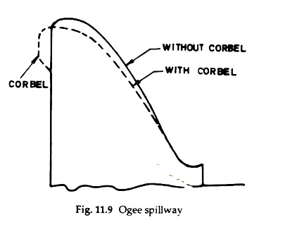
An ogee spillway has a control weir whose profile is as shown in Fig. 11.9. The upper part of the spillway surface matches closely to the profile of the lower nappe of a ventilated sheet of water falling freely from a sharp-crested weir. The lower part of the spillway surface is tangential to the upper curve and supports the falling sheet of water.
The downstream end of the spillway is in the form of a reverse curve, which turns the flow onto the apron of a stilling basin or into the spillway discharge channel. Ogee spillway is generally used for concrete and masonry dams. It is ideally suited to wider valleys where sufficient crest length may be provided.
The profile of an ogee spillway is designed for a given design discharge (or corresponding design surcharge head). When the flowing discharge equals the design discharge, the flow adheres to the spillway surface with minimum interference from the boundary surface and no access of air to the underside of the water sheet.
The discharge efficiency is maximum under such condition and the pressure along the spillway surface is atmospheric. If the flowing discharge exceeds the design discharge, the water sheet tends to pull away from the spillway surface and, thus, produces sub-atmospheric pressure along the surface of the spillway.
While negative pressure may cause cavitation and other problems, it increases the effective head as well as the discharge. On the other hand, positive hydrostatic pressure will occur on the spillway surface, if the flowing discharge is less than the design discharge.
An upstream overhang, known as corbel, is added to the upstream face of the spillway as shown in Fig. 11.9. The effect of the corbel is to shift the nappe (and, hence, the spillway profile) backward which results in saving of concrete.
If the height of the vertical face of the corbel is kept more than 0.3 times the head over the crest, the discharge coefficient of the spillway will be practically the same as if the vertical face of the corbel extended for the full height of the spillway.
Type # 3. Side Channel Spillway:
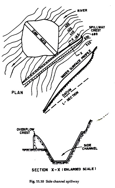
The control weir of a side channel spillway (Fig. 11.10) is located alongside and approximately parallel to the upstream portion of the spillway discharge channel which itself may be either an open channel or a closed conduit or an inclined tunnel. The spillway discharge flows over the weir crest and falls into a narrow trough (i.e., the upper reach of the discharge channel), and takes an approximately 90° turn before continuing into the spillway discharge channel.
The control structure of a side channel spillway generally consists of an ogee crest which, in plan, may be straight, curved, semicircular or U-shaped. The overflow section may be broad-crested instead of ogee-shaped.
Side channel trough is usually of trapezoidal cross-section with minimum width to depth ratio. Higher width to depth ratio would result in poor diffusion of the increasing incoming flow with the channel flow due to relatively shallow depth. Moreover, the amount of excavation would also increase for larger bed widths.
While the flow in the side channel trough should preferably be subcritical, the flow in the discharge channel is supercritical, and a control section downstream of the trough is provided by either constricting the channel width or raising the channel bottom- Because of spatial flow conditions, the depth of flow in the side channel trough would never be the same at different sections.
Type # 4. Chute Spillway:
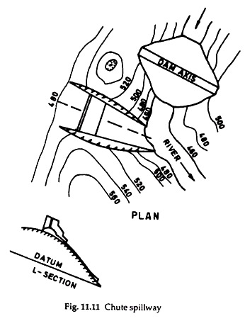
In a chute (or trough) spillway, the spillway discharge flows in an open channel (named as ‘chute’ or ‘trough’) right from the reservoir to the downstream river. The open channel can be located either along the abutment of the dam or through a saddle (Fig. 11.11). The channel bed should always be kept in excavation and its side slopes must be designed to be stable with sufficient margin of safety. As far as possible, bends in the channel should be avoided.
If it becomes necessary to provide a bend, it should be gentle. The spillway control structure can be an overflow crest, or a gated orifice or some other suitable control device. The control device is usually placed normal or nearly normal to the axis of the chute. The simplest form of a chute spillway is an open channel with straight centre line and constant width.
However, very often the axis of either the entrance channel or the discharge channel is curved to suit the topography of the site. The flow condition varies from subcritical upstream of the controlling crest to critical at the crest and supercritical in the discharge channel.
The chute spillway is ideally suited with earth-fill dams because of:
(i) The simplicity of their design and construction,
(ii) Their adaptability to all types of foundation ranging from solid rock to soft clay, and
(iii) Overall economy usually obtained by the use of large amounts of spillway excavation for the construction of embankment. The chute spillway is also suitable for concrete dams constructed in narrow valleys across a river whose bed is erodible for which ogee spillway becomes unsuitable.
Type # 5. Shaft Spillway:
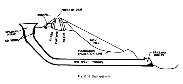
In a shaft spillway (Fig. 11.12), water enters a horizontal crest, drops through a vertical or sloping shaft and then flows to the downstream river channel through a horizontal or nearly horizontal conduit or tunnel. A rock outcrop projecting into the reservoir slightly upstream of the dam would be an ideal site for a shaft spillway.
Depending upon the level of the rock outcrop and the required crest level, spillway may have to be either constructed or excavated. The diversion tunnels, if used for river diversion purposes during construction, can be utilised for discharge tunnels of the spillway. Radial piers provided on the spillway crest ensure radial flow towards the spillway, and also provide support to the bridge which would connect the spillway with the dam or the hill.
Shaft spillway with funnel-shaped inlet is called “morning glory” or “glory hole” spillway. One of its distinguishing characteristics is that near- maximum capacity of the spillway is attained at relatively low heads. Therefore, shaft spillway is ideal when maximum spillway discharge is not likely to be exceeded.
Because of this feature, however, the spillway becomes unsuitable when a flow larger than the selected inflow design flow occurs. This disadvantage can be got rid of by providing an auxiliary or emergency spillway and using shaft spillway as service spillway.
Type # 6. Siphon Spillway:
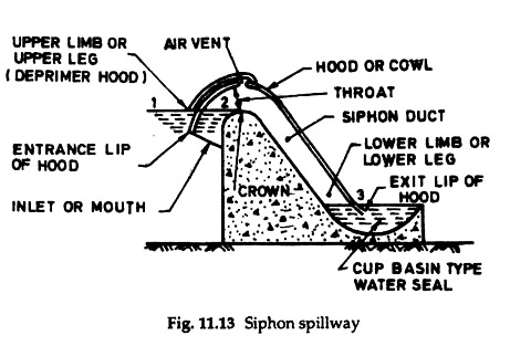
A siphon spillway (Fig. 11.13) is essentially a closed conduit system which uses the principle of siphonic action. The conduit system is in the shape of an inverted U of unequal legs with its inlet end at normal reservoir storage level. When the reservoir water level rises above the normal level, the initial flow of water is similar to the flow over a weir.
When the air in the bend has been exhausted, siphonic action starts and continuous flow is maintained until air enters the bend. The inlet end of the conduit is placed well below the normal reservoir water level to prevent ice and drift from entering the conduit. Therefore, once the siphonic action starts, the spillway continues to discharge even when the reservoir water level has fallen below the normal level.
As such, a siphon-breaker air vent is always provided so that siphonic action can be broken once the reservoir water level has been drawn down to the normal level in the reservoir. Siphon spillways can be either constructed of concrete or formed of steel pipe. The thickness of the wall of the siphon structure should, however, be sufficiently strong to withstand the negative pressures which develop in the siphon.
Besides being an expensive structure and of limited capacity, siphon spillway has a serious disadvantage due to the occurrence of sudden surges and stoppages of outflow as a result of erratic siphonic action, thus causing severe fluctuations in the downstream river stage.
A minor crack in the cover of the siphon would interfere with the siphon. Therefore, spillways are usually constructed in batteries so that the entire spillway is not affected even if cracks have developed in one or few units.
In addition, the structure and foundation have to be strong enough to resist vibration stresses. Further, there exists a possibility of clogging of the siphon due to debris and floating material. Like other types of closed conduit spillways, siphon spillway too is incapable of handling flows appreciably greater than the designed capacity.
As such, siphon spillway, whenever provided, is used as a service spillway in conjunction with an auxiliary or emergency spillway. In canyons of small width and small flood discharge, the suitability of a siphon spillway should always be examined.
Type # 7. Cascade Spillway:
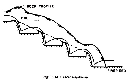
In case of very high dams, the kinetic energy at the toe of the dam will be very high and the tail water depth in the river may not be adequate for a single-fall hydraulic jump or roller bucket stilling basin.
Narrow and curved canyons consisting of fractured rock would not be suitable for trajectory buckets. In such situations, especially for high earth and rock-fill dams for which spillway is a major structure, possibility of providing a cascade of falls with a stilling basin at each fall (Fig. 11.14) must be considered.
The cascade spillway is likely to be an ideal choice for high rock-fill dam for which the material has been obtained from a quarry located downstream of the dam so that the flood waters may be discharged over the quarry face. As the quarry would usually be excavated in benches, these may as well form the steps in the cascade.
Cascade spillway is being provided at 218 m high Tehri dam on Bhagirathi river in the Ganga valley of the Central Himalayas. At Darmouth dam in Australia, the spillway to pass 2700 m3/s of flood discharge would be an unlined cascade in granite. The benches of the cascade will be 5 m high and of varying widths to suit the topography of the site.
Although a cascade spillway, during floods, would be an attraction, it may not be always acceptable for environmental reasons which demand that the quarries be always located upstream of the dam and below the normal water surface level of the reservoir so as to cause minimum disfigurement of the land.
Type # 8. Tunnel Spillway:
Tunnel spillway discharges water through closed channels or tunnels laid around or under a dam. The closed channels can be in the form of a vertical or inclined shaft, a conduit constructed in an open cut and backfilled with earth materials, or a horizontal tunnel through earth or rock.
In narrow canyons with steep abutments as well as in wide valleys with abutments far away from the stream channel, tunnel spillways may prove to be advantageous. In such situations, conduit of the spillway can be easily located under the dam near the stream bed.
